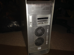
Rear shot of the G5 DP 1.8 GHz

Front shot of the G5 1.8 GHz
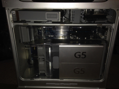
Inside shot
Original case and guts, 1,8 GHz Dual Processor
Stock Nvidia 5200 64 MB video card

Fans removed
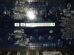
The model number for the dual 1.8 GHz board
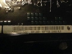
630-6691

The original heatsinks for this mac
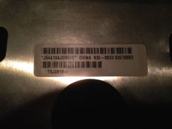
Heatsink model number A
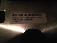
Heatsink model number B

The stock Nvidia 5200 64 MB

Loosen these allen screws 5 turns
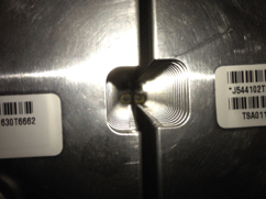
And these two

And these ones

This one too
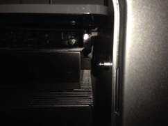
Don't forget about this one

Last but not least, this one also
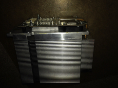
CPU A pulled out

CPU B pulled out

Processors removed
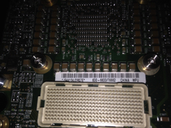
630-6633/T6662 CPU A (PowerMac G5 1.8 GHz)
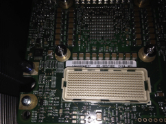
630-6633/T6662 CPU B (PowerMac G5 1.8 GHz)
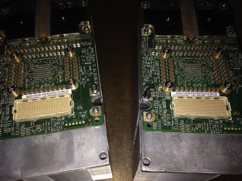
Both 1.8 GHz CPU's side by side

Apple 820-1592-A to be put in

This is the 630-6692 board. For a dual 2.3 GHz G5, all the important info about it

The replacement board

New CPU's

New heatsinks to be put on. I couldn't find a match

Top of the new heatsinks

This is what was supposed to cool the CPU's i'm putting in
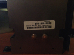
Heatsink 630-6682 #1

Heatsink 630-6682 #2

630-6464/T6489 (PowerMac G5 2.5 GHz) CPU A
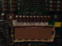
630-6464/T6489 (powerMac G5 2.5 GHz) CPU B
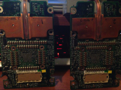
Both together
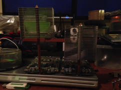
Old vs new, 2.5 GHz has a taller rear pipe

Old heatsink with copper core

Old heatsink with copper core
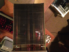
New heatsink with heat pipes
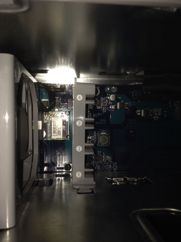
To remove old logicboard, I removed the PCI brace first

Unplugged the speaker and fan

PCI fan pulled out
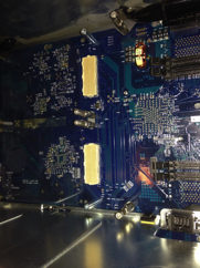
Heatsink standoffs to be removed
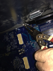
Gently used a pair of pliers and twisted counter clockwise

Just enough to be unscrewed by hand afterwards
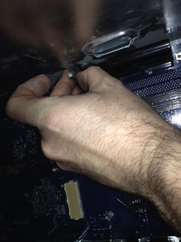
Unscrewed the rest of the way by hand
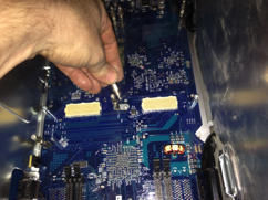
First few removed

They all need to be removed in order to remove the logicboard
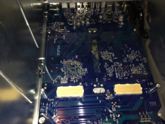
All standoffs removed

Use a screwdriver to remove these last screws
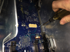
Almost out
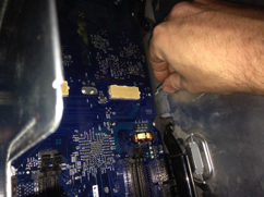
Pull out by hand and repeat for the other side

Unplug IDE cable
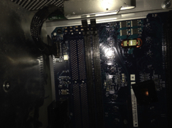
Gently remove cap for front panel cable

Gently unplug front panel cable. Careful, it will break easily
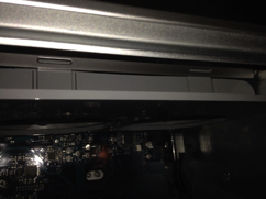
Rear fan assembly comes out next

Push in the two tabs and the fan pops out
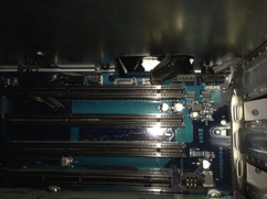
All fan and SATA cables unplugged from board
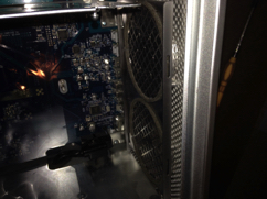
Rear fans removed

Motherboard screw #1 to be removed

Motherboard screw #2 to be removed
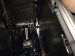
Motherboard screw #3 to be removed (this one holds the PCI divider in place)
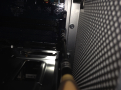
Motherboard screw #4 to be removed

Motherboard screw #5 to be removed
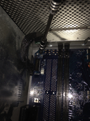
Motherboard screw #6 to be removed
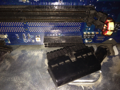
Unplug power socket A

Unplug power socket B
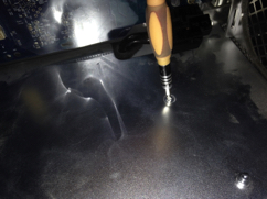
Unscrew PSU cover screw #1

Removed and set aside

Unscrew PSU cover screw #2

Removed and set aside
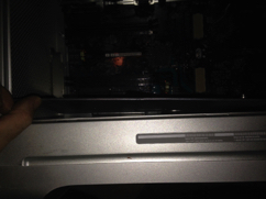
Lift up on the PSU cover

Start pulling up at an angle

Only way it comes out is if you bend it slightly

Pulled out and set aside
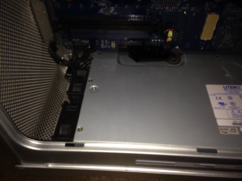
PSU cover removed
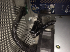
Power socket C location
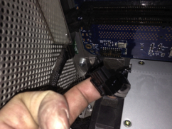
Unplug power socket C
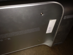
Bottom 2 of 4 PSU screws to be removed
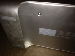
Bottom 4 out of 4 PSU screws to be removed
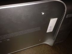
Removed and set aside

Removed and set aside
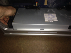
Slide PSU forward and start to lift up at an angle
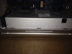
Once lifted out at an angle, PSU just pops out
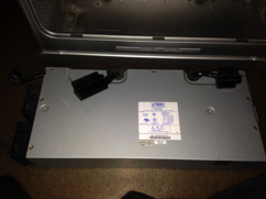
PSU removed

Inside the PSU area
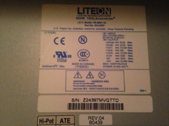
LiteON 600W, one of the better PSU's for a G5
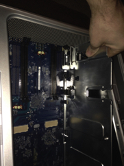
Grab board by PCI divider and pull slightly towards the front of the case to remove
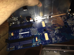
Lift at a slight angle and the board comes free
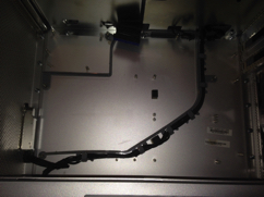
Inside the case. I added a couple of old G5 rubber braces to sit under the CPU sockets for support
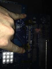
Remove these screws to take off PCI divider from board

This screw also comes out
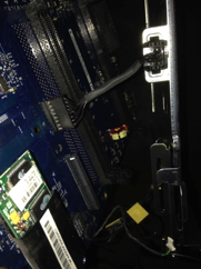
Unplug the fan connector from the logicboard
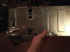
PCI divider free

Old vs new logicboards
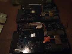
Slight differences on the underside
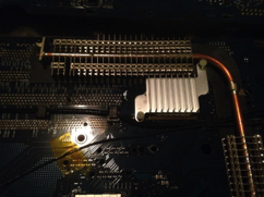
New board has a heatsink on this chip

New board has copper on this chip
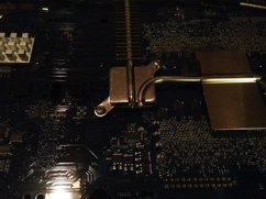
Old board has aluminum on this chip

PCI divider attached to new board
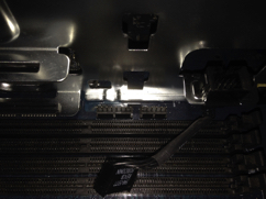
Plug front fan connector into socket close to Airport slot
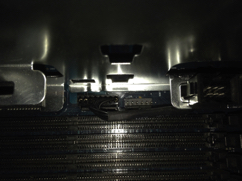
The other connector is what the old liquid cooler plugged into (nothing goes there now)
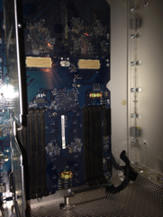
New board put into case (reverse on how you took out the old board)
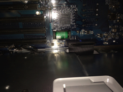
Plug in the IDE cable

Plug in the fan and SATA connections
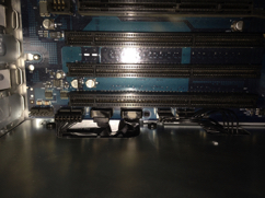
All connections plugged in. And screws holding the board in place are put in too

Slide PSU in at an angle

Once it pops in, slide it back a little and it will seat properly

Plug in power socket C

Plug in power socket A
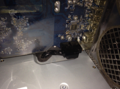
Plug in power socket B
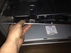
Put in PSU cover. With a little effort, it does go in
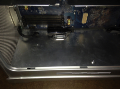
It will sit flat, readjust to put the screws back in
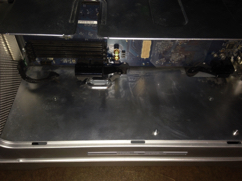
Screws back in place
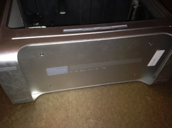
Bottom PSU screws back in place to hold PSU
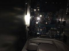
Slide PCI fan back in place

Reconnect speaker and fan plugs
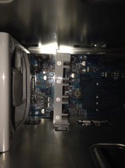
Put back in PCI bracket and it's two screws

Replace the cards you took out from the old board

Ram going into the machine
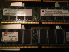
8 sticks of ram, to be installed, ram has to be in pairs

More ram
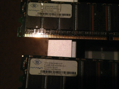
More ram

More ram
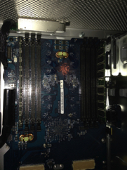
First pair (sockets A1 & B4)
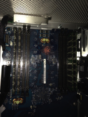
Second pair (sockets A2 & B3)
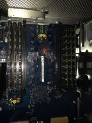
Third pair (sockets A3 & B2)

Fourth pair (sockets A4 & B1)
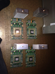
All four CPU's sitting together
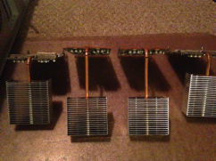
Rear heat pipe differences
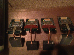
The 2.5 GHz CPU's have copper on the bottom, the 1.8 GHz have aluminum
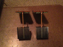
Old CPU's set aside. We will be working with these ones

New heatsinks. Too bad they both didn't have copper bases

New heatsinks side by side

This is what the old heatsink looked like

Reinstall rear fan bracket

Plug in it's connector near the SATA ports

Arctic Silver 5 used on this project
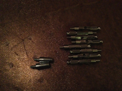
Standoffs and screws to be put back in
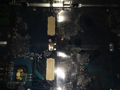
Going back into their original spots. Tighten but don't snap them off
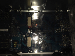
All put back into place
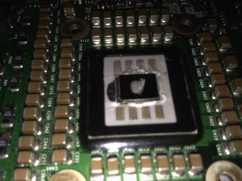
Just a dab on CPU A

Same with CPU B
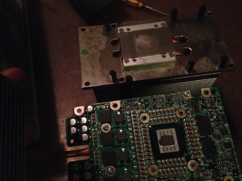
Start with CPU A. I put it on the aluminum heatsink

Make sure it sits flush and properly with the plastic board holders

Reinstall CPU screws, tighten in X pattern until snug. Do not over tighten
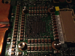
Screws snug
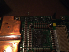
Screw in screws that hold the CPU board into place
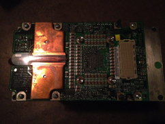
Finished CPU
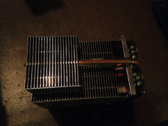
Rear pipe as tall as the heatsink

Put this CPU in the bottom socket
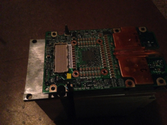
Now work on the next CPU

Tighten screws in X pattern until snug. Remember, do not over tighten

Screws holding board onto heatsink in place
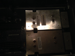
Plug this CPU into the upper socket
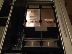
Replace front fans

Make sure the front panel plug is plugged in or no power button

Also replace plastic cap on front panel plug

Put baffle back into place. Start up machine to see if it chimes and boots. If so, take allen screwdriver and tighten standoff screws so CPU's don't shift. Tighten until snug
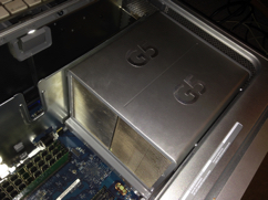
Once everything works, put plastic spacer and cover for the heatsinks
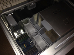
Replace front fans and baffle. Put side back on machine and boot up

Before you use this machine, you will need to recalibrate your CPU's by using the AHT 2.5.8 CD from Apple


