PowerMac 9600 mod
Written by JJ Arthurs
Monday, 02 August 2004
This was based on the idea from Accelerate your mac. A G4 in a 9600 case.
(http://www.xlr8yourmac.com/systems/g4_agp_in_9600_case/G4_agp_in_9600case.html)
*This is a reprint of the mod, since the pics were taken 4 days after the mod was completed.*
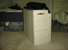
First of all, I was given a 9600/300 Powermac and I decided to redo it with a little spunk because it was pretty slow when I got it. This is what the computer looked like when I got it originally. Pretty bland if you ask me. Lets spice it up on the inside and give it some serious horsepower.

Taking off the plastics was fairly simple, as stated on the website I followed. Pressing the release tabs on all plastic parts but had to be careful not to break off any of the tabs that would be needed to put the plastics back on the metal housing.
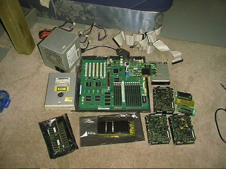
I took out all non-essential parts IE the logicboard, floppy, ect. I might be selling them on eBay when i get the chance.

I also took out the original motherboard plastic standoffs by pressing in behind the metal casing to release them and i used a pair of pliers to break off the metal standoff that you screw the motherboard into place with. The red circles are where the PC mounting holes were marked, the blue circle is where the metal standoff was removed and the yellow circles is where the power switch will be mounted.

I dremeled out the inside of the case that folds up using high carbon cutoff wheels on a dremel. I think I went through 40 cutoff wheels altold doing this job. To accommodate the high cpu heatsink and to give it breathing room, I dremeled out the rear cross pattern to allow more airflow and better access to the power supply.

I also dremeled out holes for the front USB, case feet mounting holes, and a portion to allow the motherboard to sit properly without hitting the onboard sound.

Next I created the mounting plate for the power supply to be held in place. I used the bottom of an old AT PC case because it was the only spare metal I could find laying around. I measured the template from the stock 9600 power supply using a sharpie marker. Then using the cutoff disks, cut out the holes.

The smaller hole on the mounting plate is to hold an 80mm Thermaltake turbine fan to keep the upper compartment cool, and not overheat the cpu. This is a picture of the power supply and turbine fan mounted to the bracket.
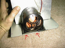
I had to cut the turbine fan a little on the bottom base to allow clearance for the folding case lid to close properly.
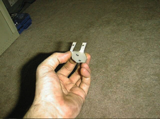
I made a bracket for the front power switch from the same case that i cut the power supply bracket from, utilizing the front stock power button.

Here is a pic of the power switch mounted on the bracket I made. I used an old 386 power switch, opened it up, took out the latch hook to make it a momentary switch.
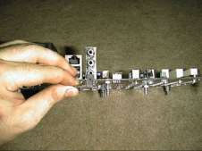
In order to mount the motherboard to the case i used 1/4 inch bolts that are 1 inch tall. The 9600 motherboard stood 1 cm from the case itself, so I had to use 3 nuts on the bolts to simulate the same height as pictured here.

Then from there I used a couple of pci usb cards to align where I wanted the mounting holes drilled. Thanks to another site online, I took the idea for a modified sharpy pen, and drew the spots onto the metal case for where I had to drill the holes.
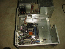
Here is a pic with the motherboard, power supply and power switch mounted and placed within the aligned mounting holes. Everything looks like it fits and it all lines up properly.

Not much was done to the outside of the case, I tried to keep it as stock as possible because I liked the look of the big huge bulky case, but I did put in a front USB bracket so I can plug in my Mass storage camera for quick retrieval of my pictures.

I kept the original mount for the side 120mm fan so it can pull out the hot air from the motherboard compartment. I used a 3-pin to 4-pin adapter plug that I had laying around to give the 120mm fan power so it wouldn't draw excess power from the motherboard itself.
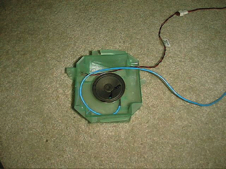
I got rid of the original large mac speaker because it made a loud ticking sound and replaced it with a normal speaker found in modern PC's. The ticking sound problem was solved.
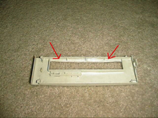
Due to me using an LG DVD Burner, I had to sand down the cd bezel a little on the top inside to let the door pass without any problems. LG for some odd reason makes their drives just a little larger than Pioneer does.
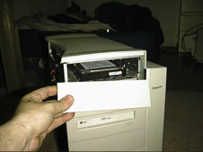
Since I don't use a floppy drive, I put my main hard drive in it's place, and used a blank bezel instead of the floppy bezel. I could have used the floppy bezel, but I didn't like the fact that had a hole in the center of it. So I used the blank that was laying around.
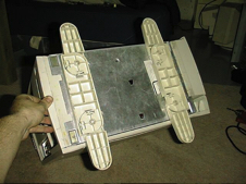
I attached a pair of case feet from an old server I had to give the new case some better stability. Now this tower won't rock if I accidently bump it.
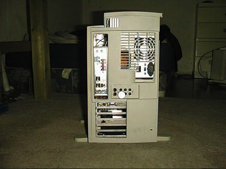
The back of the case was slightly modded due to the misaligned power supply. (my fault) As for the rotary switch, that is used for the turbine fan so I can make adjustments on how cool I want the cpu compartment to be.


